Lipo voltage monitoring with FrSky D-Receivers without sensors
Here I’d like to share a simple Lipo voltage monitoring setup, that I’m using in my Bixler with an FrSky D8R-XP receiver. No sensors or other electronics are required - only a single servo cable and two resistors, total value of about 50c + some soldering.

The FrSky D-series receivers have a great feature: the analogue telemetry inputs, called A1 and A2. On some receivers both are freely accessible (D8R-XP, D8R-Plus), on others the A1 port is hardwired to the internal receiver voltage, but the A2 port is always accessible for external connections (D4R-II). On those ports, a voltage of up to 3.3V can be connected. It is measured internally (0-3.3V = 0-100%) and transmitted via the telemetry uplink to your transmitter. Using a simple voltage divider soldered from two resistors, one can monitor the main battery voltage of a model (or any other voltage).
Theory Link to heading
The electrical scheme for such a divider looks like this (source: Wikipedia):
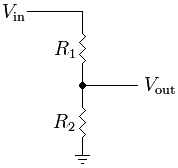
Vin is the positive connection of out battery (+), and Vout is the divided voltage. The resistors R1 and R2 are chosen in such a way, that the maximum output voltage will be less or equal to 3.3V (the maximum voltage that can be directly applied to the A1/A2 ports):
$$ V_{out} = \frac{R_2}{R_1 + R_2} * V_{in} $$
I’ve chosen \( R_1 = 22 kOhm \) and \( R_2 = 4.7 kOhm \). This allows to safely measure voltages up to 4S (16.8V fully charged):
$$ V_{max} = \frac{4.7}{4.7 + 22} * 16.8 V = 2.96 V $$
Hardware Link to heading
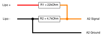
I’ve soldered the voltage divider on a servo cable, so it can be directly connected to the A2 port of my D8R-XP. The connection diagram looks like this:
Software Link to heading
Finally, minimal settings are needed in the transmitter to process the A2 telemetry value correctly and accept it as the main model voltage, with the corresponding warnings for low and critical voltages. The A2 range (maximum value) needs to be set up correctly - in my case to 18.75V (3.3V max at A2 port divided by the voltage divider factor, which is 4,7/(22+4,7) = 0,176; 3,3 / 0,176 = 18,75). The telemetry config page for my Taranis in Companion9X looks like this:
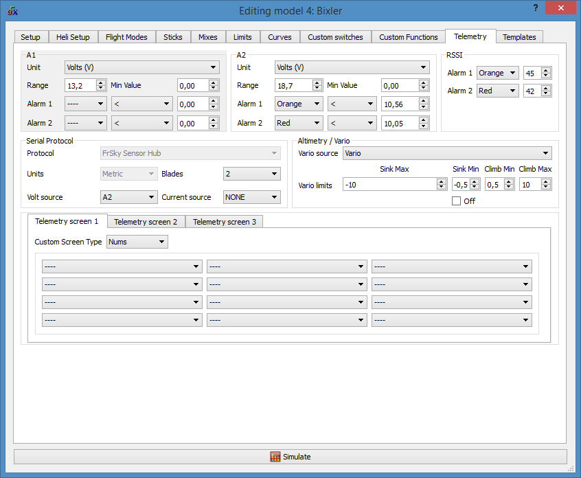
Important thing is to choose A2 for “Volt source”. This makes Taranis show the A2 voltage on the main display screen, instead of the normally shown receiver voltage (A1).
The warning values as shown are setup for a 3S Lipo, which is what I’m flying in the Bixler. The divider is safe to use up to 4S; with other resistors chosen correspondingly, 6S and more is possible as well, however the measurement resolution will go down somewhat as the divider factor goes up.