Pipeline stoplight: making a GitLab CI pipeline status visible
A question I often run into in our trunk-based project at work is:
Can I push onto the current master, or is it broken again?
Yes, one should primarily concern oneself with the root cause of this question even existing and attempt to fix it, but I’m afraid in this project it’s a lost cause. So instead, I’ve taken to the next best thing I could think of: preventing myself and fellow team members from pushing more changes on a red pipeline and making things even worse™.
Introducing the Pipeline Stoplight, or: “Don’t push unless this thing is green”:
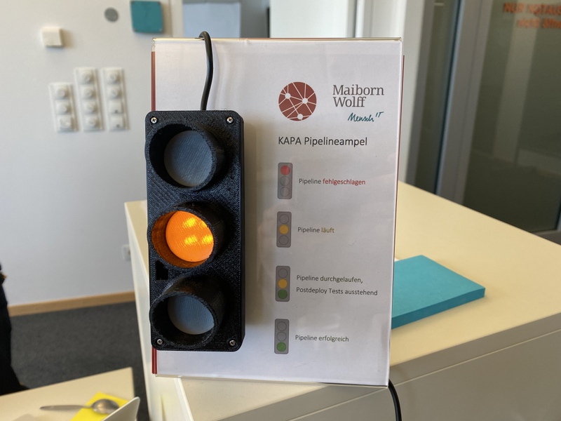
Making it was a nice, fairly simple DIY exercise combining the following aspects:
- 3D printing (the casing)
- Electronics (simple circuit design and soldering)
- Arduino programming (reading the pipeline status from the GitLab API via WiFi)
Physical design Link to heading
The stoplight casing is straight from page 1 of a Thingiverse search for “stoplight”:
Mini Stoplight (Programmable ATTiny85 Arduino AVR) by Montiey
The author designed it to house an ATTiny85, but I wanted to run my stoplight on a NodeMCU or a similar WiFi-equipped Arduino-compatible board. Thankfully, the casing was easily big enough to accomodate what I chose.
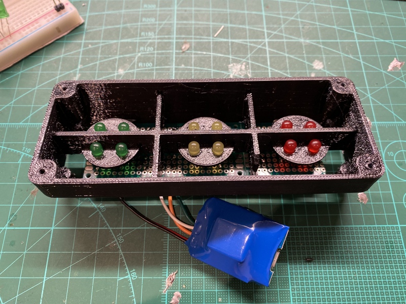
The choice of filament for the casing was guided by whatever was already loaded in the printer, which happened to be black PETG. In hindsight I should’ve gone for PLA - it prints faster and is less glossy. For the transparent-ish LED covers, black would not do, so I switched to “natural” color semi-transparent PLA. It works well enough to diffuse the light from 4 LEDs to a single “lamp”.
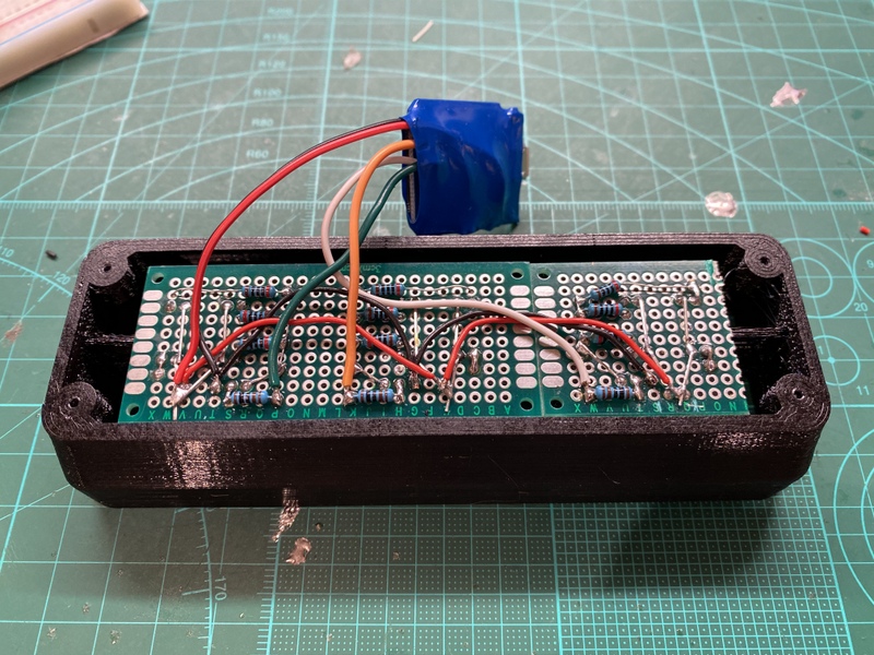
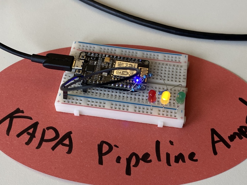
I used a cheap 4x7cm soldering board and a half to hold the LEDs and the supporting circuitry, and attached the WeMos D1 Mini (the controller board I ended up using) with wires, secured from accidental shorts with heatshrink. The insides look like this:
Circuitry Link to heading
The original prototype for the stoplight was much smaller, and much simpler from the electronic point of view:
It was just the NodeMCU (lacking a D1 Mini at the time, but it’s basically the same thing, just larger), three resistors, three LEDs and a piece of wire. Each LED was wired directly to a digital output pin in series with a resistor.
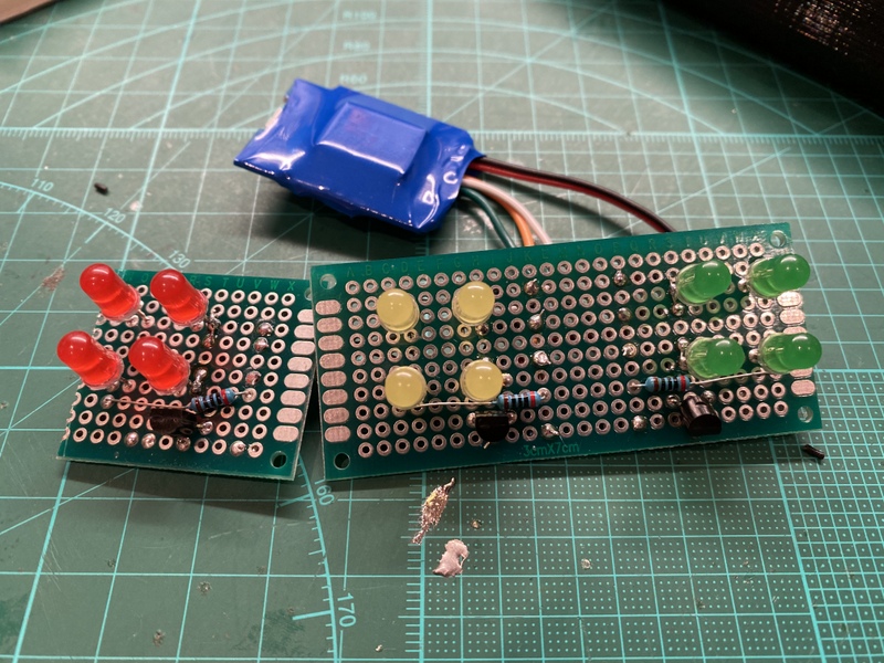
The big stoplight uses four LEDs per light instead of one, to get a level of illumination at least sort of visible from across the room. The problem here is, each pin of a NodeMCU (or a D1 Mini) can only output a small amount of current - not enough to power more than a single LED at anywhere near maximum brightness. To get around this problem, smart people have come up with a circuit like this:
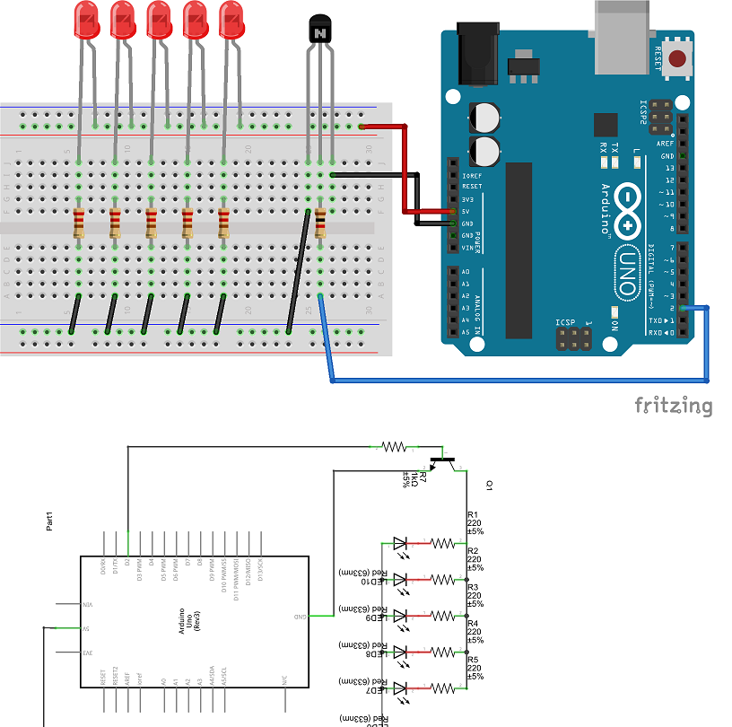 (image source: The Customize Windows)
It powers multiple LEDs directly from an Arduino’s 5V supply pin, which can provide a much higher current than a digital output. The LEDs are switched on and off using a transistor, whose base is wired to the digital output instead via a high-value resistor. This way, there is only a tiny current needed at the digital pin to switch a higher load (the LEDs).
The WeMos D1’s 5V pin is directly connected to the USB connector’s power, so the same trick can be done with it. I basically copied this circuit layout three times, adjusting the exact component placement around my 4-LED clusters and the available space on both sides of the soldering board. It isn’t exactly pretty, but it works just fine. The resistors I used are 1 kOhm between the digital pins and transistor bases, and 200 Ohm in series with each LED.
Code Link to heading
The code I wrote for this thing can be found here:
Same as the circuit - it’s not the prettiest, but it’s simple and it works. The dependencies you need are:
Arduino core for ESP8266 WiFi chip to run the whole thing on a NodeMCU, D1 Mini or any other ESP8266-based board. To install this, you need to add the library URL to your Arduino Board Manager:
https://arduino.esp8266.com/stable/package_esp8266com_index.json.ArduinoJson to deserialize GitLab API responses and extract the pipeline status. This can be installed and included directly via the Arduino Library Manager.
Fill out the settings at the top, and flash it on a compatible board. Connect via Serial Monitor to check that it works - it’ll connect to WiFi and start polling the pipeline status, outputting some debug info along the way.
Green+yellow and error states Link to heading
Alongside the obvious SUCCESS (green), RUNNING (yellow) and FAILED (red) statuses this code has a fourth one
that’s less obvious: RUNNING_TESTED (green+yellow). It is activated when the pipeline status returns scheduled. We
use it, because our pipeline has a delayed “postdeploy test” step that runs 5 minutes after the main pipeline, giving
the software enough time to fully restart after it was redeployed. These tests very rarely fail, so it’s kind of OK to
push when the pipeline isn’t “fully green” but has already completed everything except the postdeploy tests - hence
green+yellow on the stoplight.
There’s also ERROR (blinking red, when status check fails) and UNKNOWN (blinking yellow, when the status is different
from anything the code checks against).
Feel free to use the status model exactly the same, ignore the ones you don’t need (scheduled pipelines won’t typically
appear in a project by themselves). Or build your own states and light combinations - it should be straightforward enough.
Future improvements Link to heading
Based on the reception in my team, I’ll probably build a couple more of these in the near future. Some improvements I might incorporate include:
Brigter LEDs. The standard yellow and red ones are fine on 5V with a 200 Ohm resistor behind them, but green is barely visible when the office is in bright daylight. I might use lower-value resistors and crank the LED currents all the way up on the greens, or use some sort of “ultra-bright” ones.
More powerful hardware for more sophisticated checks. I originally wanted to implement more states with a fairly complex logic that looks not just at the state of the whole pipeline, but checks single stages instead (have the unit tests passed already? deployment? etc.), but the 80 KB of RAM on the ESP8266 isn’t enough to parse the JSON responses from the GitLab Jobs API when the pipeline has more than a couple jobs (and ours can have several dozens). An ESP32 might be more up to the task.
That’s it really. Hit me up on Twitter if you decide to build one of these, or with any comments you may have.